Telephone: 408-839-5569
Email: (Click Here) Andrew@JaguarSpecialties.com
Last Update 7-2-24
|
The devil is in the (wiring) details......
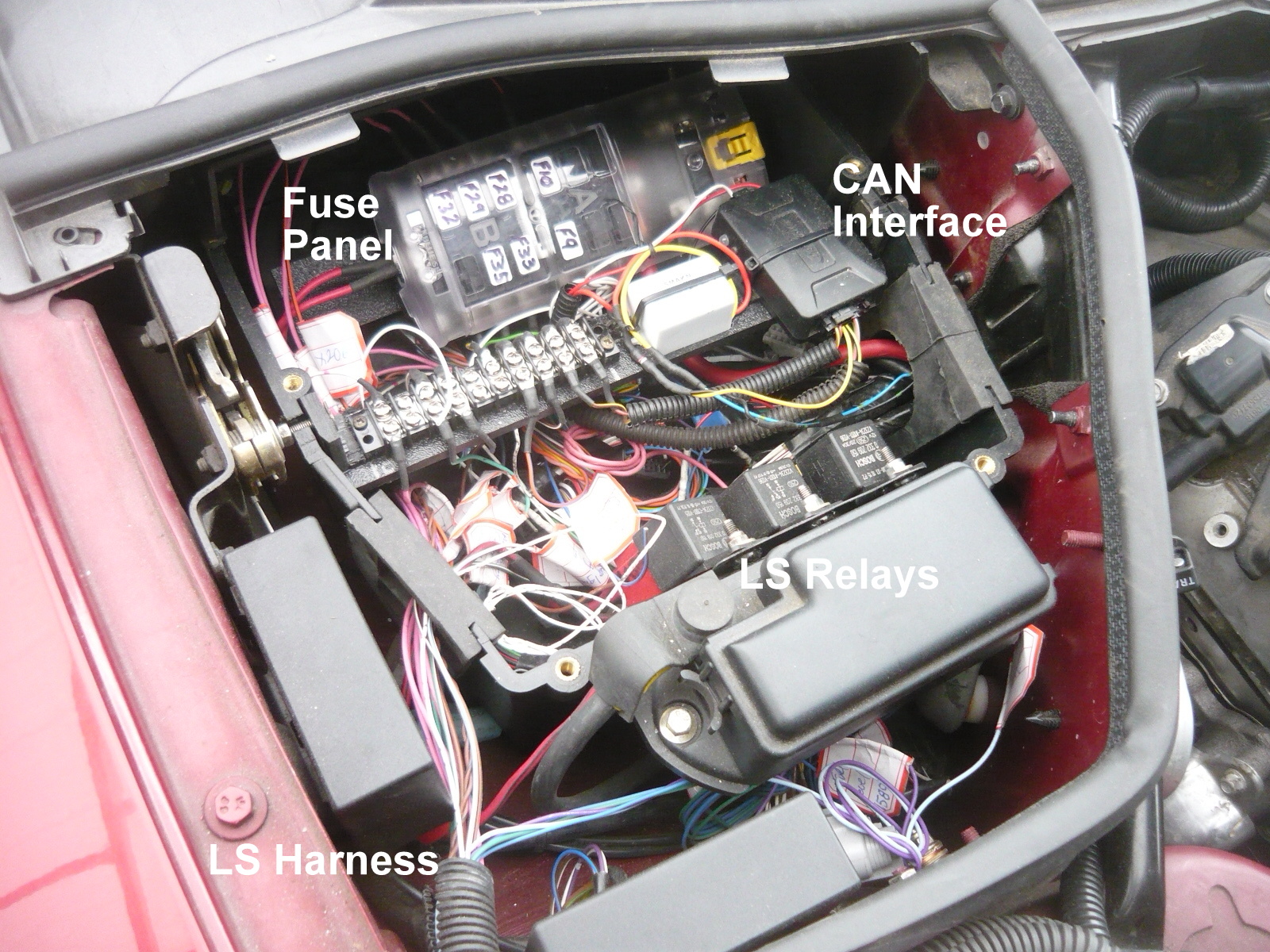
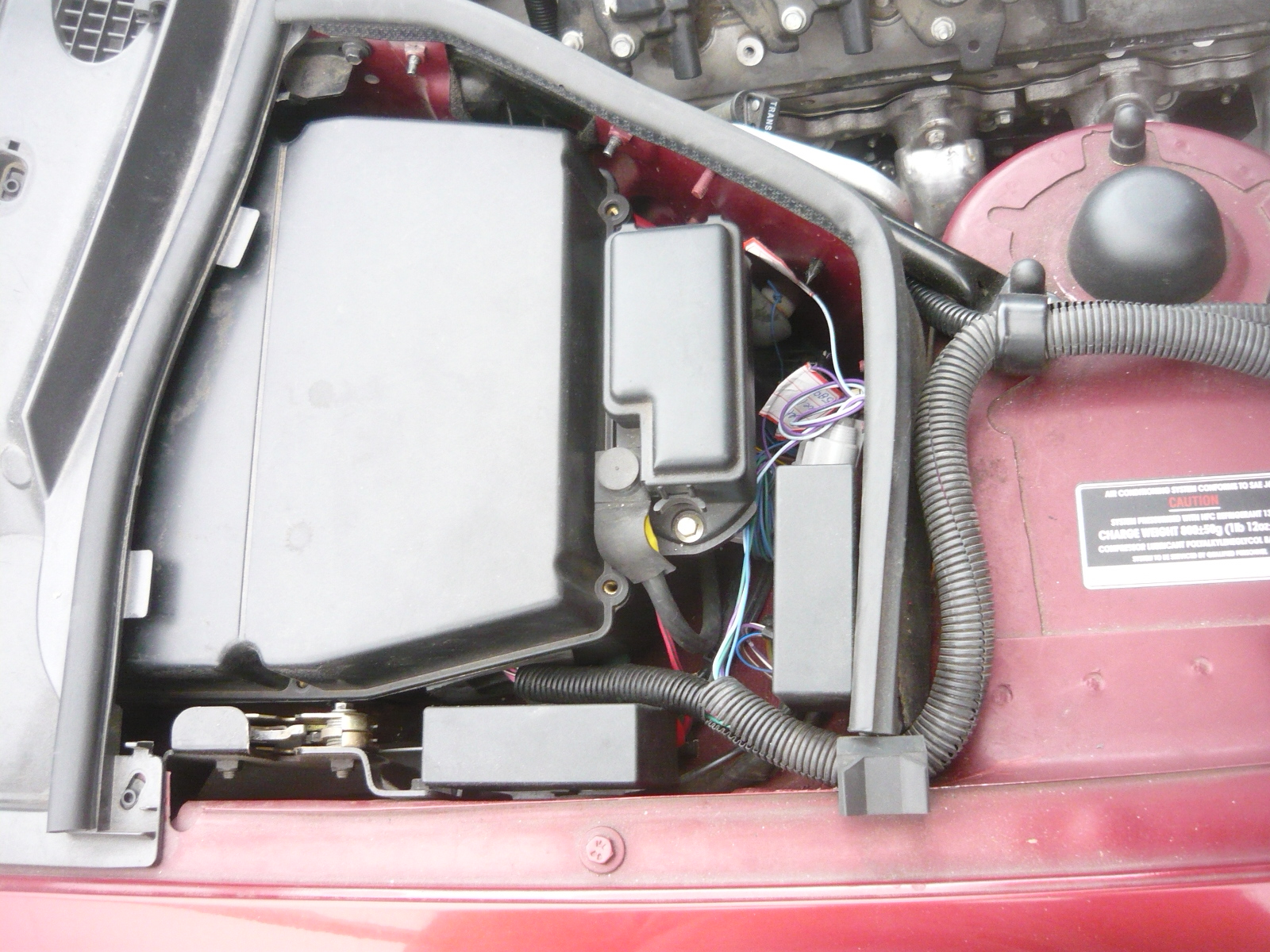
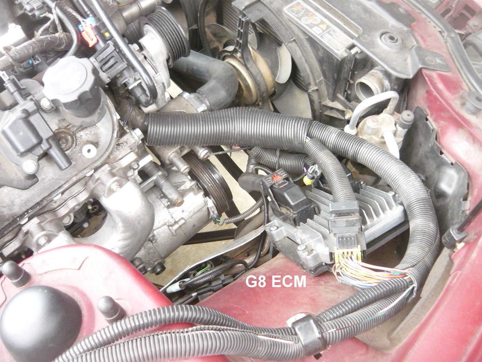
Part 4 - Getting into the wiring.......... Go on to Part 5 - Exhaust (Click Here) (This is the fourth in a series of articles on installing the later Gen4 LS engine packages in our Jaguar cars. Check back from time to time for an update) So for the most part, LS is just LS and I anticipated that much of the knowledge our from previous LS-XK8 conversions would (in general) apply here too. But if there are any key areas of this (Gen4) L76/6L80E conversion that would absolutely be different, one would definitely be the wiring. Here's the skinny on that: LS Electrical, Wiring, and Controls - Before getting into this part it's most important to stress that wiring work (and even the minor rework of modifying a factory harness as needed here) requires only the best documentation, and that means using the right service manuals. GM publishes complete service manual sets for all of its cars, including the G8, and they offer far more critical detail than any of the aftermarket books (Haynes, etc.,.) or even CD's. These books, while maybe a bit expensive, are the only ones that offer the much needed info (in all areas, but particularly wiring and electrical) to make this all work. And on top of that there is a huge amount of other troubleshooting and repair info that also comes in the set, so we always use (only) these books. Without a doubt, much progress has been made in the way of engine and trans controls as compared to the older Gen3 LS installations we had done before. This is 2009 drivetrain (compared to our previous newest LS drivetrain, 2002) and it's amazing where it's all gone. For these applications, the engine control module (ECM) does so much more than earlier LS controllers (displacement on demand, etc.,.), but the controller itself is actually about half the size of the earlier units. And in the original G8 engine compartment, the ECM is mounted right front, not that far from a hot radiator and right exhaust manifold. Since it is small, it can fit in tighter spaces and is still contained in an environmentally sealed and finned box. Small size- easy to tuck away. But the real kicker is that the transmission control module (TCM) on the Gen4's is a separate unit and actually sits inside the trans itself. I didn't actually realize that before I started this project, but it makes sense. GM moved to the CANBUS control architecture in around 2006, so all of the different modules around the car are connected on a 2 wire network to speak in software code to each other. Those 2 wires link the ECM to the TCM and they can communicate all they like (the wires also go to the diagnostic connector so we can scan and monitor the system for repairs, troubleshooting, etc.,.) Getting back to the XK8, we removed the original Jag ECM and TCM from their enclosure (right rear of engine compartment) and this is where (previously) we would mount the LS ECM. However, in this install the G8 ECM will remain in the engine compartment right front area in its original (G8 style) location, and the Jag ECM enclosure will then house only the required fuse box to power the L76 wiring harness and some other small items (like our Jag-GM CANBUS interface, etc.,.). Here are some pics for you to follow along- first of that enclosure all empty and bare, then with the new fuse panel and other pieces installed and almost complete, the original compartment cover installed, and then the ECM mounted right front- nice!! . . Note- this fuse panel allows multiple connection points for battery power, ignition power, and grounds as needed. It has a clear molded cover that can be labeled as needed and fits the area nicely. In the pic showing it mounted in the compartment you can also see a simple terminal strip (above and forward of it) that I use to make connections between the LS harness and the car. Using high temp (steel) ring terminals there makes for durable reliable connections that can easily be disconnected for testing, etc.,.
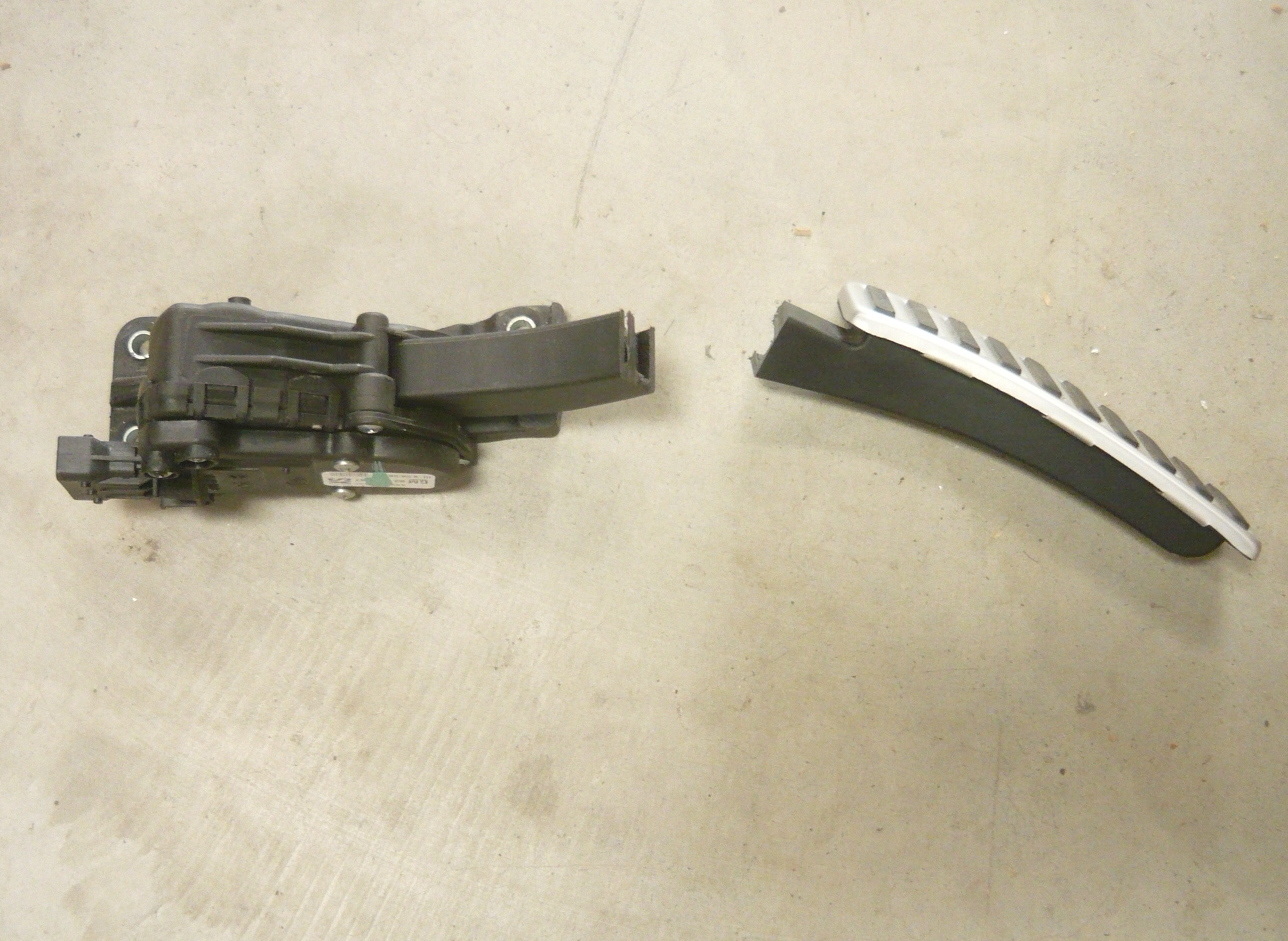
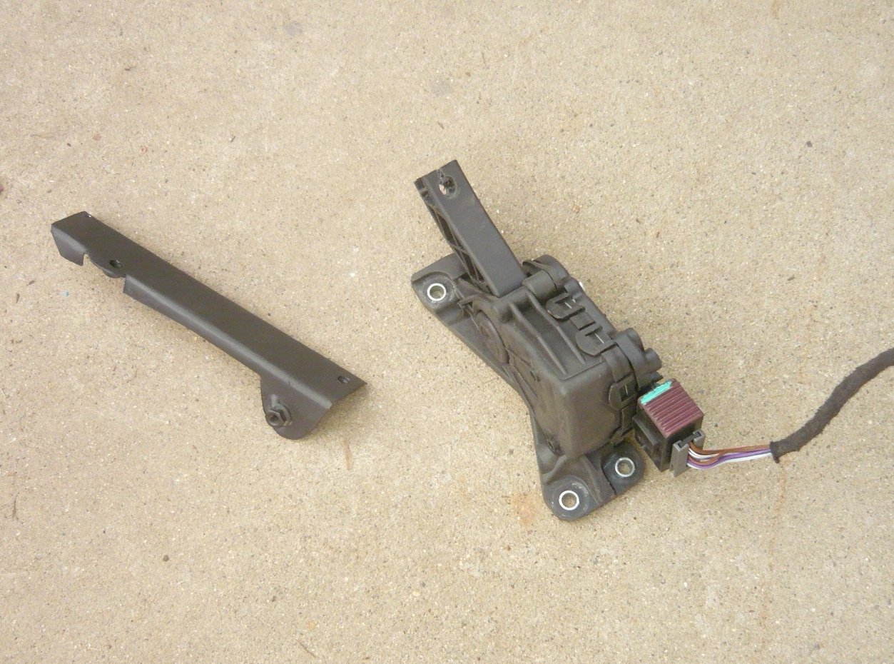
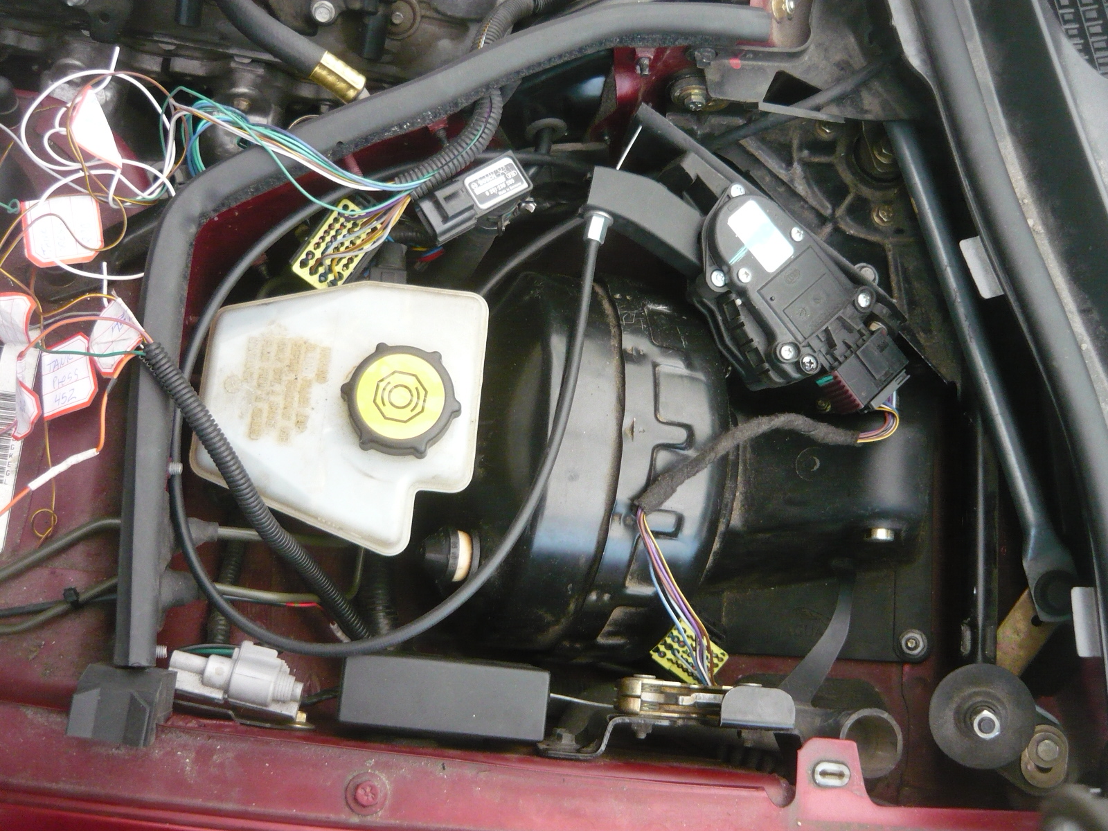
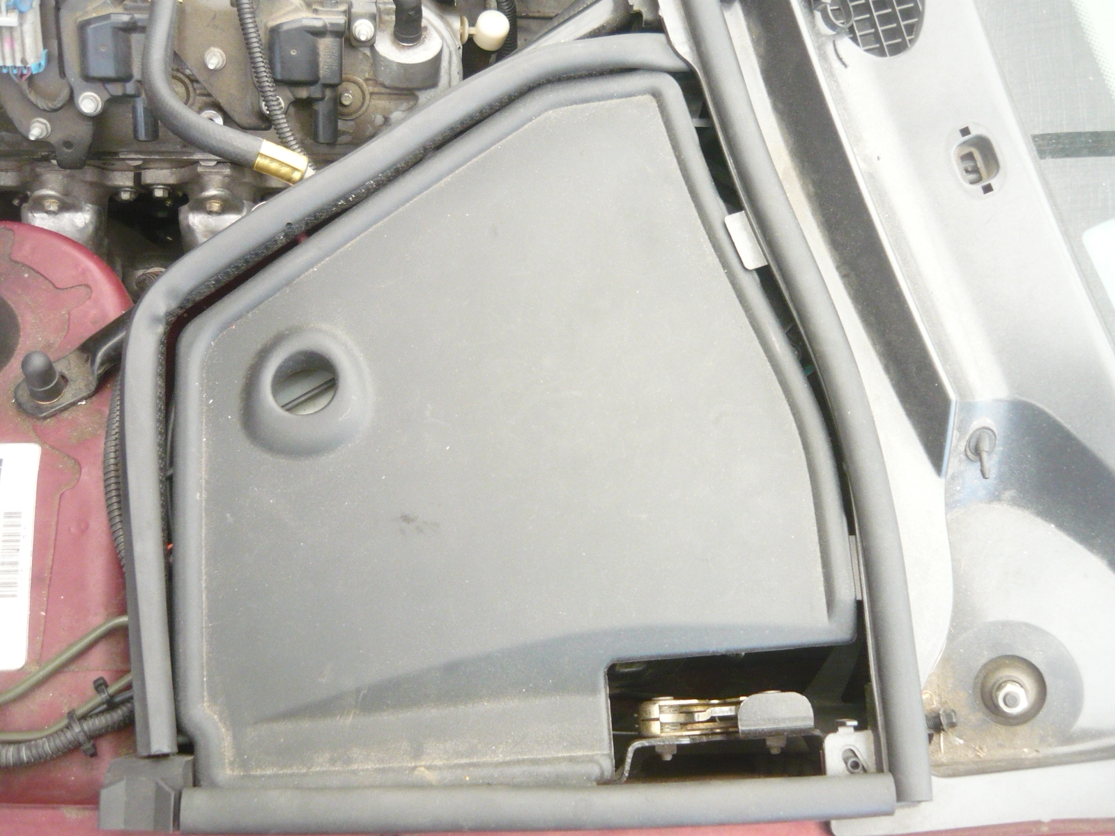
Harness details- Along the lines as other conversions we've done before,. we use the factory G8 wiring harness on the Jag. Some minor adjustments/changes were needed, but nothing major. Using the factory books as a guide, all of the key inputs to the harness were identified and labeled for later connection on the car. From there it was a simple task of making the various connections for battery and ignition power, grounds, fuel pump control, etc.,. When finished it all still looks very much like factory GM wiring, mostly because that's what it is... Drive By Wire (DBW)- Believe it or not, this is the first conversion we're doing that uses an electric accelerator pedal with no mechanical link to the throttle body (no throttle cable). Below are some pics of the standard G8 pedal assembly (which was much too big to mount in the XK8 foot well). Instead, the pedal unit itself was modified (foot pad cut off) and then mounted with a bracket in the engine compartment, actuated by a short cable from the standard Jag pedal. It took a little doing to get the correct throw on the DBW assembly but it ultimately worked perfectly, and everything hides in the brake master cylinder area of the engine compartment. Interestingly, in 2003 when Jaguar upgraded the XK8 to the newer 4.2 engine, they went to a purely DBW system as well that also kept the older style pedal under the driver's foot and then connected with a short cable to the electronic unit in the brake master area.. Below are some pics of the standard G8 pedal assembly and then the installation onto the XK8. In the installed pic you can see the short throttle cable coming up from the firewall and looping around to the DBW assembly. The final pic shows everything hidden under the stock compartment cover (I tidied up all that wiring at the same time...)
Other electrical- The remaining electrical/control aspects of the installation are pretty basic- the alternator will be controlled by the L76 ECM as it was originally and the ALDL (OBD2 diagnostic) connector will be mounted in the passenger footwell (a convenient spot). There is no need here to mount any park/neutral switch on the shifter (as in other installations) as that is done internally to the transmission. Other than that, the addition of the large diameter battery style cables from the starter and alternator to the car itself completed the electrical side.
That's it for this update. In the next installment we'll start looking at the driveshaft, shifter, and exhaust Want an LS-powered Jaguar for yourself?? Click the links below to Jaguar-LS conversion information on our website and a also photos of many different completed cars, most by our customers:
Gallery of completed LS-power Jags: http://www.jaguarspecialties.com/LS-gallery.asp
|